Anyway. The signal from the VSS is sent to the speedometer board. On this board the signal is buffered (amplified), turned into a square wave and the frequency is divided by two. This buffered signal is fed to the ECM and the cruise control module (87/88 4 cylinder Fieros don't have a cruise module, instead the ECM does that job as well).
If your cruise works, the VSS and buffer/divider work. The ECM will also set a code if it does not receive any speed signals.
Now, assuming this works, the odometer should work too. This is because the buffered signal is used directly to drive the odometer motors. If they don't work, the speedo board is shot. Period.
If the odometer works, but the speedo doesn't, you may just have a bad connection on the speedo board. Let me explain the operation:
(you may skip the theory if you like)

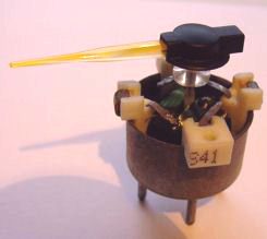
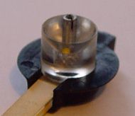
The speedo needle is driven by a so called air-core meter (the meter in the image is from an 86-88 backlit speedo: note that it is not soldered, but plugged in!). Regular meters work by a needle which is pulled back to zero by a spring and a coil forces a magnet away from the zero position if current flows through the coil. An air core meter uses two coils which are at an angle of 90 degrees to each other. These coils are called the sine coil and cosine coil. Each coil produces a magnetic field proportional to the current flowing through it. Since the two coils are at a 90 degree angle, the two fields add up to a "magnetic vector". If a magnet is placed in the middle of this field, it will point in the direction of this magnetic vector. By varying the current through the two coils, the needle can utilize all 360 degrees of the gauge.
(welcome back the entire audience)
If one of the coils has a bad connection, there will be little or no current in one of the coils. If one of the coils produces no magnetic field, the vector will point in the direction of the remaining operative coil. If this is the case (speedo steady at some fixed speed), the coil is either bad or the connection is bad. If it is the connection (usually indicated by a gauge that occasionally works fine again), clean it and you should be set.
If not, either the gauge or the air core driver is shot. The air core driver is an IC on the speedo circuit board. If you have a spare board, you can try to replace it, but you better get a new board.
If the gauge is shot, you can still reuse the circuit board and get away with getting a new gauge assembly.

Finally, there is one more failure mode that is often overlooked: the needle itself may come loose on the shaft. The result can be anything from no reading to readings that are sometimes "off". Just pull up on the needle, and see if it comes off easily. If it does, slightly press the slotted part together with a plier or similar tool, but not too much, or it won't go back on the shaft. Apply 12V to the speedo and press the needle on the shaft while the needle points to "zero". Road test vehicle and verify proper calibration. You can also apply a 60Hz sine signal and calibrate the speedo to display 54mph.
There have been visitors to this site since May 31, 2000.