DashScan II Installation
First of all, you must remove the IP-Cluster in order to install the display module into the IP-cluster.
If you want to make a clean installation using the supplied wiring harness, it is recommended to remove the dashboard. You do not necessarily have to remove the steering wheel, but it makes the job easier.
 In order to install the display module (see image to the left) in the instrument cluster,
the cluster needs to be disassembled:
In order to install the display module (see image to the left) in the instrument cluster,
the cluster needs to be disassembled:
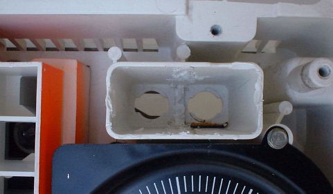
Route the display module connector and wire through the bulb hole in the rear of the housing and keep the display module in place with scotch tape. You will have to carefully enlarge the opening to get the connector through, or disconnect and resolder the wires on the module. Alternatively, you can order DashScan with the connector disassembled, see below for installation instructions.
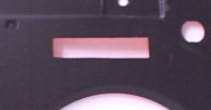
Next you need to cut a hole into the lens retainer as required to see the display (See image below for reference). You can use the front trim plate as a template. Remember you will be looking at the display at an angle from above. Draw the new opening on the lens retainer and compare the opening to the respective opening on the left side for comparison before you start cutting! A dremel tool may be useful for this, but don’t worry if the hole doesn’t look as clean as it does in the pictures, because once the red plexiglass lens is installed, you won’t see the edges anyway. Apply a small amount of black paint to the shiny edges where you cut through the metal of the lens retainer. To prevent the instrument illumination from shining through the hole, you may want to use some black tape to shield the display from "stray" light.
Now test assemble the cluster, cluster lens retainer, cluster lens and trim plate and align the display module if necessary. Align the display so that you can see all eight digits from your driver’s position at the same angle at which you can see the odometer on the left side.
If the display is in the correct position, glue the display module to the cluster (See image to the right). If you use hot glue for this, you can correct the position later if necessary. Be careful not to smear any hot glue on the displays or the rest of the cluster. After the display position is correct, glue the red plexiglass filter on the cluster lens retainer (See image below).

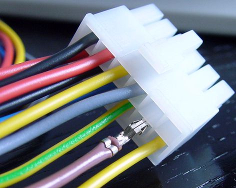
If you have a Display with a disassembled connector (for installation without enlarging
the cluster hole), look at the wiring harness mating four pin connector (see picture to the right).
It has a locking clamp and fits the harness side in only one direction. Test install the
empty connector to the harness to get a feel for it.
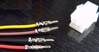
Now look at the wiring colors (yellow, tan, black and red). You have to install the display wires into the right positions in the connector, or you may damage the display! Use the mating connector (harness side) as a guide for which color goes where. After the connector is installed, the wire colors on both ends of the connectors must be identical! Be very careful doing this step, as once the connector pins are installed, you can not get them out again without a special tool!
 Installing the wires into the connector
housing is easy: just push in the display wires with the connector pins into the connector
housing until you hear and feel a "click". Pull carefully back on the wire: it should stay
in the connector.
Installing the wires into the connector
housing is easy: just push in the display wires with the connector pins into the connector
housing until you hear and feel a "click". Pull carefully back on the wire: it should stay
in the connector.
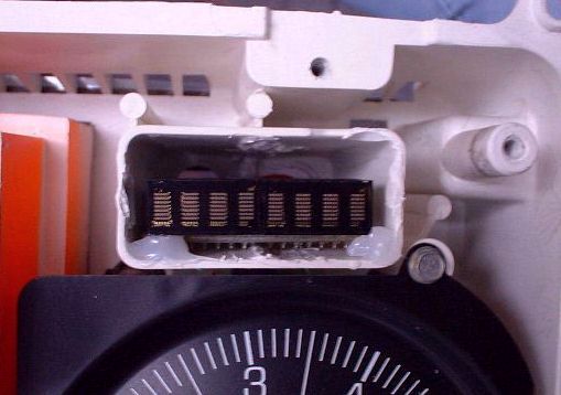
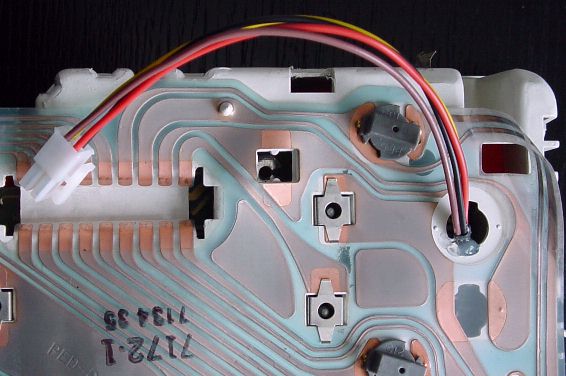
The rear of the instrument cluster should now look something like this...
Now you’re ready to put the instrument cluster back together. Installation is the reverse of the above.
Now you’re ready to install the DashScan control module.
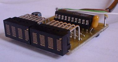
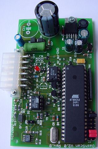 Installation of the control module (pictured on the left) is simple, but it requires some wires to be spliced.
It is strongly
suggested to refer to the Helms or similar manual to ensure the proper connections. The connections
described here may vary from vehicle to vehicle.
Installation of the control module (pictured on the left) is simple, but it requires some wires to be spliced.
It is strongly
suggested to refer to the Helms or similar manual to ensure the proper connections. The connections
described here may vary from vehicle to vehicle.
The control module may be installed in a suitable location under the dashboard. If you prefer, you can isolate the module with some tape, but that's not really necessary. Just make sure the big capacitor (that is the largest part on the board) faces "up" when the board is installed. The bottom side of the board will then be touching only the plastic steering column cover that it rests in, so nothing can happen there.
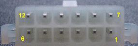
DashScan comes with a rectangular, white 12-pin Molex connector, that connects to the harness that you must install and splice into the various circuits of the Fiero. If you have a TPMS version of DashScan, there is a second connector for the connection to the TPMS receiver and a TPMS warning lamp.
The pin assignments are as follows:
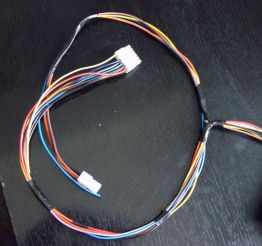 The picture on the right shows the harness that comes with DashScan II. The large
12-pin connector is the Molex-connector that plugs into the control module. The
smaller 4-pin connector must be connected to the pigtail on the display module.
The center part of the harness must be spliced to the appropriate circuits of the car.
The picture on the right shows the harness that comes with DashScan II. The large
12-pin connector is the Molex-connector that plugs into the control module. The
smaller 4-pin connector must be connected to the pigtail on the display module.
The center part of the harness must be spliced to the appropriate circuits of the car.
There are a total of 7 pigtails that need to be spliced, 6 at the center part of the harness, and one at the display module end of the harness. The wiring colors and circuits they need to be spliced to are:
Before plugging in the control module, make sure you have spliced each cable into the right circuit! Failure to do so may permanently damage the control module! If in doubt, check the service manual! The wire colors given here are the colors of the wires in my car, YOUR car may or may not use different colors for the various vehicle circuits!
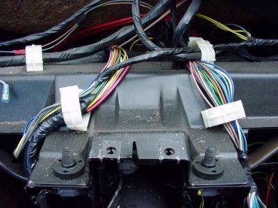
 The best way to install the harness is to splice it into the harness above the steering column.
The picture on the left shows the steering column harnesses after removal of the dashboard. The left
harness is the one that carries most of the circuits we want to tap into.
The best way to install the harness is to splice it into the harness above the steering column.
The picture on the left shows the steering column harnesses after removal of the dashboard. The left
harness is the one that carries most of the circuits we want to tap into.
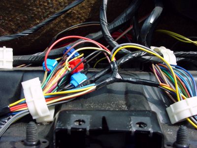
To install the DashScan harness, open the two harness clips, insert the DashScan harness with the 12-pin connector to the left, and the 4-pin connector to the right. The center part of the DashScan harness must be approximately in the middle between the two clips. The picture on the right shows the DashScan harness in place with the two clips closed again.
Now, first, the connections for operation of the trip computer have to be made:
The 12V power input (red) should be connected to a circuit that is hot when the ignition is on. I used the power to the instrument panel (pink/black). If in doubt, refer to the service manual. The splice can be seen on the picture above.
The ground connection (black) can be connected to any good ground. You can for instance connect it to the blk/wht wire going to terminal P on connector C1 (speedometer connector).
The speedometer input (yellow) must be connected to terminal U on connector C1 (speedometer connector, dk grn/wht wire).
If you want the display to dim with your driving lights on, you have to splice the lights input (brown wire) to a circuit that is hot with the headlights on. The dark brown wire from the light switch is a good choice. Check the the wiring diagrams for your specific year and model Fiero for specific information.
If the DashScan is also to be used as a scantool, two more connections are necessary. First, the ALDL control output (grey) must be extended and connected to Terminal B of the ALDL connector (wht/blk wire). The ALDL data input (green/yellow) must be extended and connected to Terminal E of the ALDL connector (orange wire).
This completes the connections on top of the steering column.
Now, one switch for operating the scantool (a.k.a. "the button") has to be installed in a convenient location which is easy to reach. Use any push button, momentary, single pole, NO (Normally Open) type switch you like. On vehicles without either the rear defogger or remote trunk release that part of the instrument pod is a perfect choice. One end of the switch has to be connected to a good ground (preferably the same splice as the ground wire). The other (switched) end must be connected to the switch input (blue wire). On the harness the switch input is the single blue wire that is next to the display module connector.
This completes the splices you have to make to install DashScan! Now your DashScan is just about operational, except for the temperature sensor(s), if you have DashScan with remote sensors. Otherwise, the inside temperature sensor is on the DashScan main circuit board and you don't have to do anything.
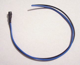 The outside temperature input is used with the optional outside temperature sensor (not
included). If the sensor is not installed, leave this input open. DashScan automatically detects the
presence of a sensor on this input. The sensor comes with pigtails, but it is not waterproof!
Seal the sensor/wire assembly against moisture, if the sensor is mounted in a place where it can
get wet! By the way, the output wire color (blue in the picture) may vary, but the ground wire is always black.
The outside temperature input is used with the optional outside temperature sensor (not
included). If the sensor is not installed, leave this input open. DashScan automatically detects the
presence of a sensor on this input. The sensor comes with pigtails, but it is not waterproof!
Seal the sensor/wire assembly against moisture, if the sensor is mounted in a place where it can
get wet! By the way, the output wire color (blue in the picture) may vary, but the ground wire is always black.
If you order this option later, you have to insert the pigtails into the DashScan connector into the right cavities yourself. Then pick a mounting location for the sensor, and extend the wiring to the supplied pigtails on the DashScan connector.
 Caution: the picture shows the installation of the remote inside temperature sensor pigtail into Pin 2,
the outside temperature sensor goes into Pin 8!
Caution: the picture shows the installation of the remote inside temperature sensor pigtail into Pin 2,
the outside temperature sensor goes into Pin 8!
It is really up to you where you mount the sensor, but it is recommended to keep the cable length to a minimum (i.e. no excess cable) and mount the sensor in a dry place without direct sunlight.
If you would like to add the sensor yourself later, that's no problem. The sensor used is a Dallas Semiconductor DS1820 in the PR35 package. The center pin of this device is the data output that is to be connected to the temperature sensor input on the DashScan connector. The two outer pins must be connected to the cable shield/ground. The DashScan end of the ground must be connected to sensor ground on the DashScan connector. You may also choose to use chassis ground on the sensor and only wire one wire to DashScan. However, there may be problems with noise immunity, and it may not work.
If you have a DashScan with with a remote inside temperature sensor, repeat the procedure for the input temperature sensor and connect the output of the sensor to the inside temperature sensor input on the DashScan module (Pin 2, shown on picture to the left).
The TPMS receiver is connected to the smaller 4-pin connector. The receiver must be modified to output the raw data received by the TPMS transmitters. One wire is soldered to ground (this is optional), the other to the receiver output. These two signals are spliced into the wires of the 4-pin connector. By the way, the TPMS DashScan was designed for the Waeco MTPM100 receiver module, orderable separately as MTPM-RX100. It is rumored that a VALET TPMS system is compatible and uses the same circuit board - that's all the info I have on the VALET unit).
The other two pins in the connector are for the connection of a TPMS warning lamp. The warning lamp comes on for a few seconds after ignition on, and then should go off. It will come back on, if the TMPS has detected a critical pressure loss in one of the tires. DashScan's lamp output connects the lamp to ground. The other end of the lamp must be connected to switched power. The DashScan TPMS connector provides switched power, but if the lamp is installed in the Fiero cluster in an unused location, chances are that power is already present there and only one wire is actually needed.
Other than that, you can install the Waeco receiver as directed in the manual. You may install the control box that came with the TPMS, but you can also choose not to and only use it for the learn process. DashScan drives the warning lamp and replicates most functions of the Waeco box.
Connect the display module connector to the display, and then connect the control module connector to the DashScan control module. Turn on the ignition: DashScan should come on and display a copyright message in the display. If this happens, the red and black wire are connected correctly. Otherwise, turn off the ignition immediately: disconnect the DashScan module and verify 12 Volts with ignition on between Pins 6 and 12.
Next, push the button. The display should change. If it doesn't, check the blue wire and operation of the switch.
Now, turn on headlights and select average speed. Push the button for more than 2 seconds and release. The brightness of the display should change. Repeat until you have chosen the desired brightness for driving at night.
Time to take the car for a spin! Select current speed and drive at steady speed. The displayed speed should be about the speed the speedometer shows. If the speed is twice the real speed, you have selected the wrong speed signal. If the speed is zero, you have chosen the wrong circuit.
Finally, stop your car. Turn off engine. Push button and hold. Turn on ignition. Release button after 3 seconds. The display should show "No Codes" if no trouble codes are stored, or display a trouble code. If the display shows "No Data!", there is something wrong with the two ALDL lines. Check control and data lines for shorts, etc.
For the TPMS version, you must first install and test the Waeco-receiver as directed in the Waeco manual. When that works, you can be sure the transmitters, receiver and antenna work correctly, and you may now remove the Waeco button/LED box.
Now you can teach the DashScan2 using the small pushbutton in the corner of DashScan and the small 3-color LED next to it. The procedure is the same as for the Waeco-control box. When you're done, DashScan should display the tire pressures when the appropriate positions are selected.
There have been
visitors to this site since May 31, 2000.