
The first version of FlexScan had a simple keyboard with a diode matrix that encoded the pressed key into a binary 4 bit representation. All debouncing and key repeats was taken care of by ScanOS. The limitation of this method was obvious: you can only press one key at a time, so this baby was limited to 12 different keys and that's it. But that's not all. I was tired of soldering umpteen tiny diodes manually that made up the diode matrix. And this simple method tied up 4 CPU port lines for a simple task. There had to be a better solution. While contemplating life on a resting spot in Yosemite national park, I came up with the idea to use a small microprocessor to do the dirty work. Yes, you heard that right! A Coprocessor for FlexScan! Yeah! Party on Wayne!
Well, quite frankly, the choice was logical. The component cost for a cheap micro is about the same for a handful of diodes. The CPU on the main board was out of IO lines, and soldering a single 20 pin chip is a lot less work than soldering all those diodes. So using a microprocessor was the logical alternative. My choice was again an Atmel CPU (hey, do I get a couple of free samples for my unsolicited advertising, or what?), this time the AT90S1200. This one is only a few bucks, readily available in surface mount (space constraints), and in-circuit programmable (if I ever decide to change the program, I wouldn't want to unsolder a 20 pin SMT chip.
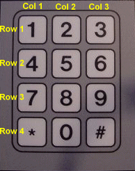
The keypad I used with this approach looks just like the old one, except that this one is actually a key matrix, which I can scan. The keypad I chose has the numbers 0-9 and the star and pound symbol. The star symbol also has the meaning of "No/Abort/Escape" and the pound symbol means "Yes/Ok/Enter". Whichever keyboard you choose is fine, but keep in mind to use this meaning to be compatible with other FlexScan applications. By the way, the Escape key actually generates ASCII-Code 27, and the Enter key generates ASCII-Code 13. All other keys (0-9) generate the ASCII-Code of that character.
But the smart keyboard chip can do more. It can also detect if key combinations are pressed, which can be used to trigger all sorts of extra functions. Suddenly, things like Alt-Ctrl-Del become possible, that is, if your keypad has those sorts of keys. Anyway, you get the idea.
To keep things flexible (hey, this is FlexScan after all), I kept the definitions for all keys and key combinations except for the naked numbers in the 64 byte EEPROM of the keyboard CPU. This way, you can define these keys and key combinations whatever you feel like (or what your keypad has printed on it). And since the program file is separate from the EEPROM file and can also be programmed separately, you can use the ISP-Connector to redefine keys as much as you please, or at least as much as the manufacturer's specified endurance is.
Also, now that I have a second CPU on board, I have free I/O lines again! I decided to connect a small piezo speaker to the board for tactile feedback, as well as a LED for general use. ScanOS provides functions that let users use these two nice features.
Luckily, the same keypad I used for the simple keyboard is also available in a multiplexed version. For 12 keys, only 7 I/O lines are needed. Decoding the keyboard input is a joke for a microprocessor. At first I wanted to stay backwards compatible, but since nobody has actually built a unit with the simple keyboard yet, why bother? Things are simpler this way.
First, I need to encode more than 4 bits, so a parallel interface was out of the question. Now that a serial interface was necessary, I chose to use a 8 bit ASCII code with no start bit, which comes to 8 bits total. Only two lines are used for transmission (both idle high/high impedance). A data line to transmit the raw keyboard data, and a clock line, that marks the data as valid. Since the FlexScan CPU has to poll these lines by software, the clock duration for low as well as high periods is no less than 5ms, otherwise the CPU might miss a bit. So, the transmission of a character takes 80ms. The bits are transmitted LSB first, and are transmitted as standard ASCII. However, ASCII-Codes with bit 7 set are reserved for special functions/meanings, like function keys, debugging functions or a soft reset.
But how do I control the piezo or the LED? Well, since the main CPU has two free I/O lines now, why not use these to transmit data to the keyboard? So, the method is similar: Normally the lines are high, but if the clock line has a high->low transision, this clocks a data bit into the keyboard CPU. This is in effect a high priority interrupt for the keyboard processor, so it is serviced immediately, which means that the main CPU can quickly transmit a byte (or more, if necessary) to the keyboard CPU. This virtual 8-Bit register is more than enough to control the piezo and LED. Since the keyboard CPU also has I/O lines left, these could be used to drive additional LEDs or other hardware controlled by the virtual 8-Bit register.
Finally! The schematics are online, click on the image to view it in full size. I'm sorry that these are hand-drawn schematics, but I don't own a CAD program, nor do I have the time to put these into electronic format other than through scanning. As you see, there is not much to this one. A few resistors, two LEDs, and a 4MHz resonator. You have to figure out yourself what goes where on the board, but I'm sure you can manage.
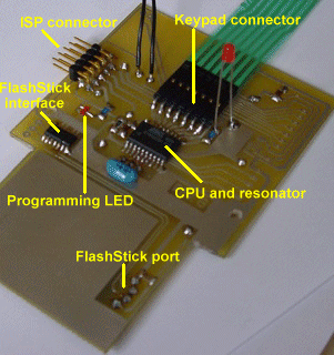
You can see from the picture on the top of the page that I put a lot more on the board than just the keyboard circuit. Reason #1 is that there was simply no more space on the main board for some things, and the basic user has no need for them anyway. The "power user" however wants to have the FlashStick port to go with the intelligent keyboard, and the board also has provisions for connecting a LCD-display, complete with contrast pot. So you have the choice of using the main board's LCD port or the one on the keypad.
As I said earlier, the codes for the numeric keys are fixed as ASCII codes 0 through 9, but all other codes can be redefined at will! This is the mapping of the keyboard CPU's EEPROM:

| Location | Keys pressed | |
| 0-8 | * + key 1-9 | |
| 9 | * + key 0 | |
| 10-18 | # + key 1-9 | |
| 19 | # + key 0 | |
| 20 | key * (Escape) | |
| 21 | key # (Enter) | |
| 22 | keys * and # | |
| 23 | keys * and # and 2 (Reset) | |
| 24 | keys * and # and 5 | |
| 25 | keys * and # and 8 | |
| 26 | keys * and # and 0 |
Hint: if a key is not used or should not generate a code, define it as $FF, this value is ignored by the ScanOS.
Here you can download the HEX-File for the Flash program memory and EEPROM range, and find the layout files and a viewer here. The keyboard assembly will absolutely not work, if you don't program something into the EEPROM memory, so at least use the EEPROM-file above for initial testing before you start changing and experimenting. If the EEPROM is blank, all keycodes generated will be $FF.
There have been visitors to this site since May 31, 2000.