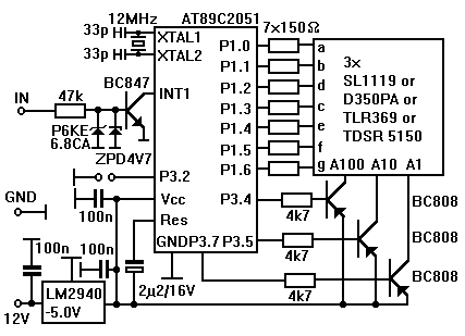
The idea for this circuit originated on the Fiero mailing list. One listmember saw a HUD-Speedo on another car and asked me if it was possible to have something like this on the Fiero. Sure, it's possible.
I came up with this little circuit that fits on a circuit board less than 2.5" x 2.5" and fits in a small box. I used Conrad Electronics P/N #522848 and it fits great. But any other box should do as well.
The circuit consists of a small microcontroller and three 7-segment LEDs. The controller is responsible for measuring the speed and driving the LEDs. The reading on the display is mirrored, and the unit should be placed on the dash facing up. That way the reflection of the bright LEDs can be read on the windshield. A good place to mount the HUD is on top of the extra gauge cluster (at least on V6's). That way the reflection will appear right next to the rear view mirror. The image is not too bright at night, but bright enough during the day for most driving conditions. After all, this is not a HUD for a $30 million F16, but only for a $1-10K Fiero (although it is almost as much fun to drive and gets better mileage too!).
BTW, a jumper is provided to select either mph or km/h, so people can use it whether they are in the US, Canada or Europe.
The voltage regulator is National Semiconductor's LM2940-5.0V, which is designed for automotive use and can withstand over- and undervoltages of +/-60V.
If you want a programmed CPU I will provide it at cost to whoever wants one, for noncommercial purposes only!

Installation is simple and only three wires need to be connected: Ground, Ignition and the Speedometer output. This is the output that feeds the ECM and Cruise Control (if equipped). Refer to the Helms manual for wiring details.
If you want to make your own printed circuit board, you can find the layout for this and many other of my projects here
A word on cooling: in the worst case with all segments on on two digits and two segments on on one digit the circuit draws around 100mA current. At a battery voltage of 14 Volts the regulator converts 0.9W max. into heat. To prevent the regulator from dying of overheating (actually it shuts down, but you want the HUD to work under all conditions, right?), you can either
- Put a resistor in the power supply line. A 47 Ohm/2W resistor brings the "heater" down to 0.4W
- Provide sufficient cooling (a little piece of metal with good thermal contact will do)
- Use a switching regulator instead. This is the best solution, but also more expensive as it requires special parts.
Here is the parts list:
AT89C2051 with program "HUD"
12 MHz crystal
3 LED displays, SL1119 or D350PA or TLR369 or TDSR5150 or similar
LM2940-5.0V
3x BC808 SMD
BC 847 SMD
ZPD4V7 SMD
P6KE6.8CA
7x 150 Ohm SMD
3x 4k7 Ohm SMD
1x 47k Ohm SMD
2x 33p SMD
3x 100nF SMD
2,2uF/16V SMD
20 pin socket