Fiero Power Window Controller Installation
Mounting and Wiring
 For mounting I chose the space behind the armrest, because it is close to the window
motor, and yet easily accessible. I also chose to use two separate controllers for the two
windows, because I didn't see much potential for common components. The only location for
a central controller would have been in the center console below the radio,
but tearing into the wiring down there would have been a major hassle.
For mounting I chose the space behind the armrest, because it is close to the window
motor, and yet easily accessible. I also chose to use two separate controllers for the two
windows, because I didn't see much potential for common components. The only location for
a central controller would have been in the center console below the radio,
but tearing into the wiring down there would have been a major hassle.
Another goal I had in mind was minimal wiring effort. I wanted to be able to go back to
stock wiring without much trouble, if I ever had to. So I decided to cut just one wire at the power
window switch, and the wiring at the power window motor connector.
The line at the switch going to the door is then connected to battery power,
the switch end of the wire is left open. This is the minimal rewiring that is possible.
Note: The power window schematics in the Helms manual are incorrect, they show switches that
are normally grounded, and one of the two wires going to the motor is switched over to
ground if the button is pushed either way. This is not the way the switch works.
Instead, both wires going to the motor are normally open, and when the switch is
moved in either direction, one line is connected to power, the other is connected to ground.
Step by step installation
Before you begin, remove the power window circuit breaker or turn the ignition to off.
The power window circuitry is only powered when the ignition key is in the run position,
so if you remove the key it's safe to work on the system. But to be even safer, you
can also disconnect the negative battery wire. But you need to reconnect power a couple
of times during the installation, so just turning off the ignition is a time-saver.
Console modification
 Begin the modification at the center console. Remove the four 7mm bolts under the
ash trays. For manual transmission cars, the shifter knob can just be unscrewed,
for automatic transmission cars, you need to remove the c-clip on the knob with a
screwdriver and just pull the knob off. Refer to the Helms manual if in doubt.
Begin the modification at the center console. Remove the four 7mm bolts under the
ash trays. For manual transmission cars, the shifter knob can just be unscrewed,
for automatic transmission cars, you need to remove the c-clip on the knob with a
screwdriver and just pull the knob off. Refer to the Helms manual if in doubt.
Next, remove the three 7mm bolts around the power window switch plate. You can now lift
up the plate and carefully remove the connector from the power window switch.
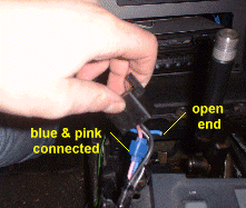
Normally you should cut the dark blue (for LH side) or dark blue/white (for RH side) wire
at the window switch connector (see image to the right for details).
Verify that you cut the right wire! The wiring colors on your car may be different!
The wire that you cut should have 12 Volts
when you push the power window switch to the "up" position.
Let me emphasize this point again: Verify the wires before you cut.
The ignition key must be on in order
to see 12 Volts on that wire! Turn the ignition off again and connect the harness end of the
wire you just cut to the pink wire going to the same switch. Leave the other cable (tan or brown)
alone. Isolate the open end of the wire you just cut going to the switch or remove that
stub from the connector altogether. You don't want this end to cause any shorts.
That's all the rewiring that needs to be done under the console! You can reassemble the
console at this point, be careful not to overtighten any of the 7mm bolts, as the
console carrier assembly has become brittle over time, and can crack easily, especially
when it's cold!
Door modifications
Next you need to remove the inner door trim. Remove the round cover under the door handle
and the Fiero crest next to the door handle with a small screwdriver. Be careful not to break
the Fiero crest. Remove the two philips head screws. Pry off the lock knob and remove the
bezel around the door handle.
Next remove the cover from the armrest and remove the three screws holding the armrest to the door.
Now comes the tricky part: Release all retainers holding the door trim to the door.
Don't force it, use a special tool for this purpose, or you may ruin your door trim!
When all retainers are off, you can put the inner door trim aside. If there is still
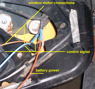
paper glued to the inside of the door, peel it off in the lower forward facing corner,
and you'll see the wiring harness coming into the door, with two thick dark blue and tan
wires going to the power window motor.
The power cable (dark blue) has switched 12V power when the ignition is on, this is because
of the connection to the pink (12V) wire that was made at the center console. The other cable is the control signal
(tan or brown wire)
and it is normally floating and goes to ground if the power window switch is pushed to "up" or goes to
battery power when the power window switch is pushed to "down". The reasoning here is that
in case that wire ever rubs through its insulation it is more likely to get grounded
than get shorted to battery. In this case, the controller will close the window
(which is better than opening it, right?).
Splicing in the new harness
 Cut these two wires in a convenient location right before the power window motor (see image
for details) and
extend the wiring to the power window controller. The dark blue wire from the door harness goes to the red "12V" terminal
on the controller, the tan/brown wire goes to the yellow "Input" terminal.
Cut these two wires in a convenient location right before the power window motor (see image
for details) and
extend the wiring to the power window controller. The dark blue wire from the door harness goes to the red "12V" terminal
on the controller, the tan/brown wire goes to the yellow "Input" terminal.
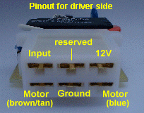
The two motor outputs of the controller must be connected
to the power window motor (the image of the connector shows which color wire goes where on the
driver's side, the motor colors are reversed for the passenger (RH) side motor!).
On some Fieros these colors are reversed for one or both sides! I don't know if
this is depends on the year or is random, but anyway you have may have to reverse the
wires if the window moves in the wrong direction after the installation is complete!
If you have the deluxe wiring harness, first you need to remove the connector from the
lock actuator motor. Don't just pull on the connector, there is a lock that needs to be
depressed to remove the connector. Once the connector is off, open the Pack-Con connector
by lifting the
latch.
Then insert a pick into the grooves shown in this
picture
to unlock the contacts. Pull on the wire to remove the old wire and contact from the connector case.
Now insert the new
connector wire
into the connector and close latch again. Then reconnect the connector to the motor.
After the installation is complete, verify that the colors are the same on your car, or you may have
to reverse the motor connections. Make sure the harness does not interfere with any moving
parts of the door, especially the door lock rods.
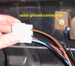 Connect the "ground" terminal to a good ground. I used the bracket near the mounting location
for this purpose, but that may not be the best conceivable location. You may want to extend the wiring
through the door into the cabin and ground it there. Whatever you choose, make sure the
resistance is well below 1 Ohm. Tie the connector end of the new harness to the door
with a wiring loom or something similar. Wrap the new harness with black tape and it
will look stock, plus it will make the new harness "stiffer" and help it stay in place.
Connect the "ground" terminal to a good ground. I used the bracket near the mounting location
for this purpose, but that may not be the best conceivable location. You may want to extend the wiring
through the door into the cabin and ground it there. Whatever you choose, make sure the
resistance is well below 1 Ohm. Tie the connector end of the new harness to the door
with a wiring loom or something similar. Wrap the new harness with black tape and it
will look stock, plus it will make the new harness "stiffer" and help it stay in place.
Be sure to use proper size wiring when extending the power motor wires, and make sure you really
have a good ground. Leave the "reserved" terminal on the controller open, it is for prototype
diagnostics only.
Now carefully verify the following:
- There is power across the ground and 12V terminals with the ignition
on, and no power with the ignition off.
- Connect a test light between the "input" terminal and ground terminal: light must be off
- Light turns on when the power window switch is pushed to "down"
- Connect the test light between the "input" terminal and 12V terminal: light must be off
- Light turns on when the power window switch is pushed to "up"
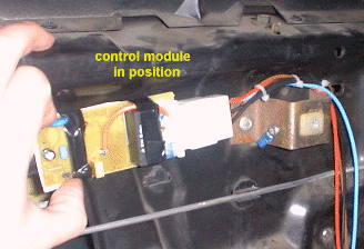
Now it's time to mount the board.
But before you mount the board, insulate it well against the metal parts of the door.
You can hot glue or tape a piece of cardboard to printed circuit board for isolation,
as there is no space for a box. Turn off the ignition and connect the board to the
connector.
Adjustment
The module senses the motor current, and if the current exceeds a certain threshold value,
the module shuts off the motor while it runs automatically.
You should set the module to the proper threshold current, because the current draw of
the motor depends on many factors like age, resistance of the mechanical components,
temperature, voltage, etc.
To determine the threshold for your motor, measure the current the motor
draws when running up or down and when hitting a stop or obstacle. Say, the motor draws 5.5A / 6A
with the engine not running/running and no obstacle, and 10.5/11.5A when it hits an obstacle.
In this case, I'd set the threshold current to 8-9 Amps. You don't want to set the threshold
too low, because then the window may not go all the way up or down if it's cold.
The desired threshold current must be divided by 5, in our example that would be 1.6-1.8, so you need to adjust
the threshold pot to have 1.6-1.8 Volts at the center pin of the pot. Measure the voltage between
the pot's center pin to ground (with the ignition key in the on position) and adjust it to the
desired level. The threshold current will always be 5x the threshold voltage set at the variable resistor.
Testing the installation & Troubleshooting
Now the big moment has come. Turn on the ignition. The relays should click. The LED should be off.
If it is on, turn off the ignition immediately and go to the diagnostic section.
Tap the window switch to "down" for a half second, and the window should go down automatically.
Tap the switch in either direction while the window is still moving, and the window should
stop. Now tap the window switch in the "up" direction, and the window should move up again.
Tap the switch again in either direction, and the window should stop again.
Press and hold the switch in one direction. The window should move, and stop as soon as
you release the switch. Repeat with the other direction.
If the direction of the window (up/down) is reversed, reverse the two connections to the window motor.
Now check if the window shuts off correctly in both directions. Tap the window switch in either
direction and observe the window. It should go up/down all the way and when the window hits
the end, the relay should turn off after about half a second. Check the other direction.
If the motor shuts off too soon, adjust the threshold current at the pot.
A common cause for problems is a bad ground, so measure resistance from the connector
ground to a known good ground. It should be below 1 Ohm.
Another problem area is the wiring. Double check everything is correct. Disconnect the
power window module, and look at the connector.
Remove the blue and brown wires from the connector by releasing the small tab on the
connector, and pulling the wires through the connector. Hold the blue wire to the red wire (12V)
and hold the brown wire to ground. The window motor should come on, and the window should
move. Reverse the connections and repeat. If the motor moves slower than before the
modification, you have a bad ground or other high resistance. However, if it does work,
it means your wiring of power, ground and the motor is correct.
Also check the yellow wire with a test lamp to ground and then to 12V.
Both times the lamp should be off, unless you push the power window switch in one direction.
It should also stay off if you push the switch in the other direction.
When everything works to your satisfaction, reassemble the door trim, and you're done!
Voila! That's all! The installation can be done in well under an hour with minimal tools.
Diagnostic Trouble Codes
If the LED is lit, the module has detected a problem. Set the diagnostic jumper and count
the blinks of the LED to determine the problem.
| Code | Description |
|---|
| 12 | Power Up complete. Note: this is not a fault condition! |
| 13 | Input circuitry faulty. This indicates a problem on the board around the LM393. |
| 14 | Input stuck to ground. This is either a wiring problem or a problem around the LM393. |
| 15 | Input stuck to battery. This is either a wiring problem or a problem around the LM393. |
| 21 | Overcurrent fault. The power controller BTS640 has shut down due to current limitation (24 Amps). |
| 22 | Short to ground or overtemperature. This problem was detected by the BTS640 power controller. |
| 23 | Short to battery. The power controller output is constantly on. |
| 24 | Over-/Undervoltage. This problem was detected by the power controller. |
| 25 | Manual Current Threshold exceeded. If the windows are operated in manual mode and the
preset current threshold is exceeded, the module shuts down the motor for 10 seconds and until the button is released. |
| 31 | ROM error. The internal ROM checksum failed. The module shuts down the motor in this case.
This may be a temporary problem because of low or high temperatures, or a defective CPU.
|