 That's what I thought that having a plug-in tester could greatly simplify troubleshooting.
I wanted to design a small box with a set of lamps that I can use to test my installation (and troubleshoot
it should I ever experience any problems).
That's what I thought that having a plug-in tester could greatly simplify troubleshooting.
I wanted to design a small box with a set of lamps that I can use to test my installation (and troubleshoot
it should I ever experience any problems).
Installing a digital cruise module from a 90's GM vehicle has become a popular upgrade for the Fiero. The Fiero Cruise Control system is vacuum operated and consists of various valves, vacuum tubing, a vacuum storage canister plus a few electrical signals to keep your vehicle at a constant speed. If any of the components fails, so does your cruise. While it's not difficult to pinpoint the problem, the system is prone to failure, and this can be frustrating.
GM recognized this and created the digital cruise control, which is independent from vacuum, because it gets its power from the alternator instead. While this innovation came too late for the Fiero, it can still be retrofitted to the Fiero. The installation is not that difficult, but it does involve quite a few wiring changes. Once you're done, everything comes down to one magic connector. Unfortunately, if you make a mistake here, the cruise will not work.
That's what I thought that having a plug-in tester could greatly simplify troubleshooting.
I wanted to design a small box with a set of lamps that I can use to test my installation (and troubleshoot
it should I ever experience any problems).
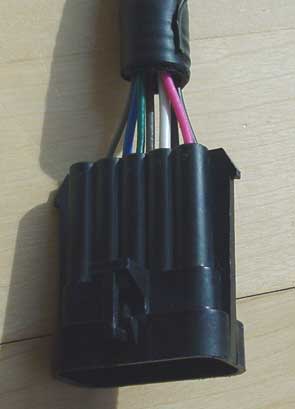
Getting the mating connector for the cruise was no big obstacle (10 pin male Metripack 150, see image to right). I'm a sucker for details, so I used about 3ft of wiring in the correct colors.
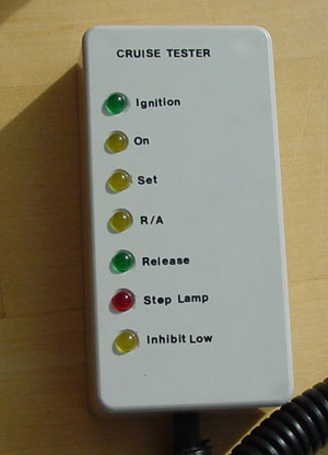
I used LEDs for all indicators, but in different colors - but you can also use all LEDs of the same color. It's important that you put a 560 ohms resistor in series with each LED. If you don't, you are going to blow the LEDs! These are the colors I used:
The color coding makes diagnosis simple: the green LEDs should come on immediately when the box is connected (with the ignition on of course). The three yellow stalk LEDs show the stalk status, and when the brake is pushed, the green release should go off and the read stop lamp LED should go on. Finally Inhibit should be the way it needs to be for your setup, so you can also use a green LED if your cruise needs inhibit to be grounded, or a red LED if your cruise needs inhibit to be open.
Two things the box doesn't test: #1 is the cruise control engaged signal. It controls the lamp in the dashboard. The Fiero doesn't have it, but if you want to hook it up, all you need to do is wire a switch to the proper circuit to illuminate the lamp. #2 is the vehicle speed signal. Granted, this circuit is important also, but if the vehicle isn't moving, this circuit will either be on or off. And you shouldn't be sitting in the trunk with this tester waiting for the LED to flash while your buddy drives you around.
 Building this box is really simple. Get any project box and drill 7 holes of 3mm each. Put the LEDs into the box,
and wire all cathodes together, except for the Inhibit LED. This common cathode goes to the ground circuit
on the connector. Put a 560 Ohms resistor in series with each LED Anode. Wire the other end of the
resistor to the proper circuits in the connector, e.g. Ignition to the ignition voltage circuit, etc.
Building this box is really simple. Get any project box and drill 7 holes of 3mm each. Put the LEDs into the box,
and wire all cathodes together, except for the Inhibit LED. This common cathode goes to the ground circuit
on the connector. Put a 560 Ohms resistor in series with each LED Anode. Wire the other end of the
resistor to the proper circuits in the connector, e.g. Ignition to the ignition voltage circuit, etc.
The Inhibit Low LED is the exception, it must be wired differently. The cathode goes to the inhibit circuit on the connector, the anode (via the resistor!) goes to ignition power. That way the LED lights if the input is grounded, all other LEDs are illuminated if the inputs are powered with battery power.
The cost is only a few dollars and the components are readily available (except for the connector maybe). It's really handy for troubleshooting your installation, but should be even more valuable when you have to troubleshoot your system in the future when your memories of the upgrade are not so fresh anymore.
Oh, and one final note: this tester should work with pretty much all digital cruises systems of the 90's with that connector. I hope you find it useful!
There have been
visitors to this site since May 31, 2000.